
In January 2021, my gray tank valve stopped working. This was quite disappointing since I’ve only had my van for 10 months and it had less than 8K miles on it. Luckily the valve was stuck in the open position, which meant my gray tank would still drain, so I decided to wait until I could address it at a later time.
As luck would have it, I met Bill Franz from Franz Customs and he was able to take care of this issue for me in May 2021. I would like to thank Bill for the following detailed description of why my gray tank valve failed and what he installed instead, which is a much better solution. I am posting this directly from the email he sent me with some minor grammatical fixes, so the rest of this post is his expert analysis, which I hope helps others who are installing a gray tank valve do it the proper way with the right kind of valve.
I do not use Solenoid valves on mobile water systems for 3 main reasons:
1) Solenoid valves will eventually have operational problems if debris/sediments are in the water.
2) Electric solenoid valves will have a run time limit (duty cycle) because they use a coil. Coils will generate heat the longer they are energized (valve open in your case).
3) They are not as reliable as Ball valves because of 1 and 2 above, plus there are more moving parts that could fail.
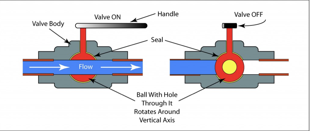
The use of a Solenoid valve is the real failure. To understand what went wrong, you need to use the diagram below. The diagram is not an exact match to the valve you had, but close enough to use for explanation. Your grey tank drain is connected to CLOSED side, which is the left side of the diagram below.

This is how it works:
1) You push the button to energize the coil on the top of the valve.
2) When the coil is energized, it creates a magnetic field that pulls the plunger up.
3) Water then flows from the left side to the right side of the valve body (input/output). This flow is the OPEN on the right side of the diagram.
4) To stop the flow you push the button again, the coil is de-energized, the magnetic field is lost and the plunger drops back down to close the valve.
Problem 1:
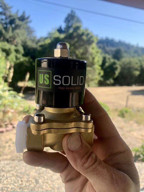
The coil is operating intermittently. When I tested the resistance across the coil, the reading would be stable and then randomly spike up and down, which explains the intermittent behavior. The coil also appears to have burn spots, or spots that are overheating. Most manufactures add a layer of protective coating around the coil winding to provide a layer of insulation from moisture or other environmental contaminates. This coating is generally uniform around the entire coil area. When coils overheat they will start to melt this coating to the point where it will start to run, like paint does when you spill it or put too much on a wall. If you look at the photo below on the left closely, you will notice that the color looks smeared and crispy, which is an indication of burning. This is generally the coating on the coil heating up to the point that it liquifies and starts seep through the insulation. I can’t say with certainty that it is burning because I don't have the same valve to compare the coil. However, I have seen coils start to take on this appearance when they are overheating and starting to burn. US Solid make really good valves so I doubt they would have Solenoid Valve coils leave a factory looking like yours. There is a cover on the coil, however, it is only held on by a single nut, and water can work its way up into the coil area, so enclosing the valve is needed when it is used outside.
The coil can also burn due to heat if the valve is on longer than the rated duty cycle. In the most basic terms duty cycle is the amount of time the valve can be on, before the coil starts to heat. The valve you had is not rated for 100% duty cycle (on all the time), so coil burning could have easily started to happen if the valve was left on for a long period of time. Because you don't have an indicator light you would not know if the drain valve was left on. Any electrical device that does not have a duty cycle of 100% needs to have a method for indicating it is on. Actually, any electrical device that generates heat should have an indicator light to let the user know it is on. In this case the valve coil is not large enough to create enough heat to start a fire, but a burnt coil is a valve that no longer works.
A coil can also burn if water gets into the coil and creates a short. A coil is a long piece of wire that is coiled, this coiling creates resistance, and resistance creates heat. If water is introduced into the coil it can create shorts in the coil, which add more resistance and burn the coil. The valve was mounted at a low point under your van and water could easily make it onto the coil housing.
I looked up the specifications for the valve you had and I found it has an IP65 rating, however, if the valve is mounted outdoors it needs to be enclosed. On the same page is an overheating warning and a statement that says the valve is NOT 100% duty cycle, which means it can’t be left on or it will overheat.

Problem 2:
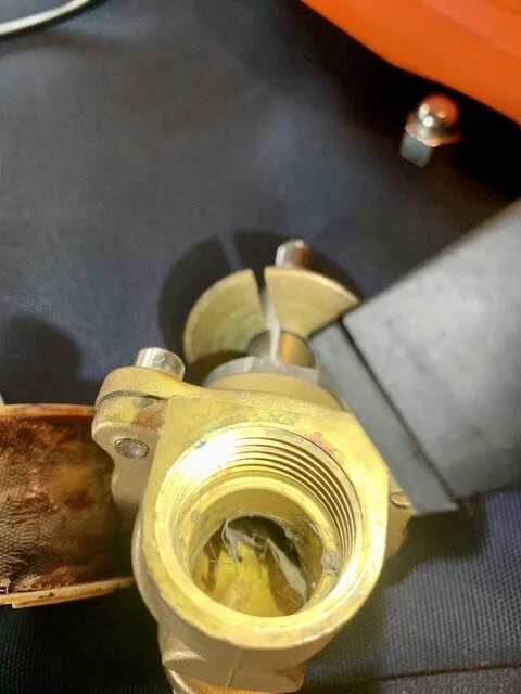
The photo above on the right is the outbound side of the valve. You will notice hair is lodged inside. Both the inbound and outbound port had hair and sludge lodged between them. This stopped the plunger from operating correctly, which explains why you saw the dripping and thought your tank was empty. This happened because it is hung up on the input side, so the hair never made it out of the valve. When this happens, the valve will start to collect debris like a spider web. A ball valve will not do this because the design uses a simple hole in the ball.
I installed a US Solid Stainless Steel ball valve with auto return and I added a water proof connector to it.
* The valve will return to the closed position if power is lost.
* The electronics are sealed so it is splash resistance from all angles.
* It has a very low power consumption when fully open (no need to worry about accidentally leaving it on).
* Full flow when open so it would take something at least 1/2” to clog the valve.
* It is stainless steel and I did this because it will resist corrosion better than brass will. Corrosion comes in many different forms when dealing with drains and it was about 10 bucks more than brass.
The diagram below is what a ball valve looks like, which you now have an electric version of. Instead of the handle, there is a small motor that turns the stem. When you depress the button, the motor turns the ball and the water flows through the 1/2” hole in the ball. This is a simpler design over the Solenoid valve and is less likely to clog when minor debris are in the water. There is also nothing for hair to snag on like there is in a Solenoid vale. Some ball valves have a smaller diameter hole, and this is generally done in pressurized systems, but you don’t need a controlled flow because your tank is a gravity drain for dumping water. This is the portion when I reference full flow. You have a 1/2” drain pipe so water will flow as fast as 1/2” can dump the water.
Below is a picture of your old valve on the input side (water entering from your tank). This is where the valve makes the 90 degree turn up, which uses water pressure to help move the plunger up when the valve is opened. You can’t see the plunger portion but the hair becomes lodged in that top areas.

Photos below are the cover over the coil. The picture on the left is what it looks like installed and this is also the same position it was mounted under your van. The picture on the right kind of shows the open area under the coil cover where water can works its way in. On a really rainy day or wet road, the underside of your van becomes a hurricane and water will eventually make its way into the valve cover. There is no seal, so simply removing the bolt on the top allows the cover to be removed.

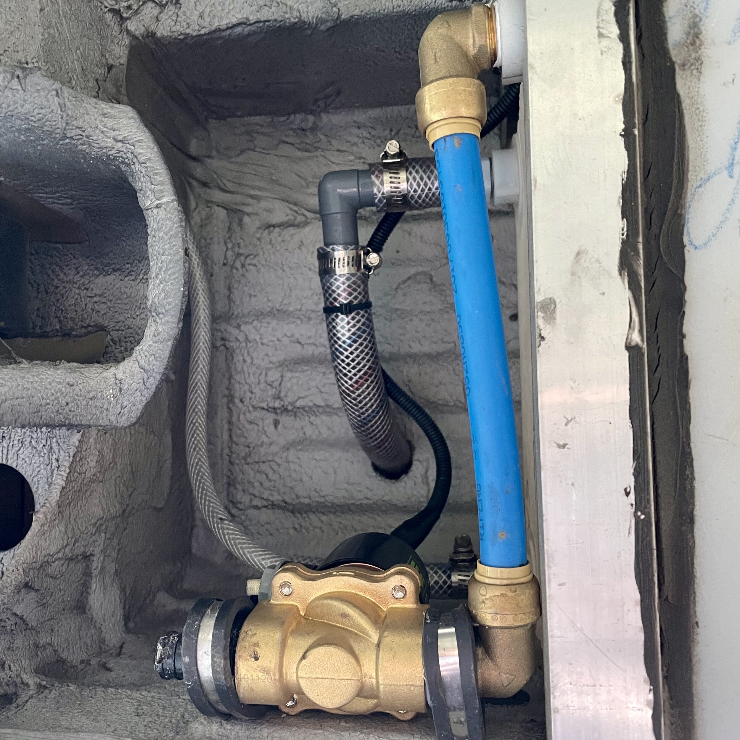
Below is your new ball valve installed. The blue pipe is 1/2” PEX that is connected to the ball valve with a 1/2” 90 degree shark bite connector. That white portion on the picture above is called a reducer sleeve. This sleeve reduces the 3/4” fitting on the valve to 1/2”, so the PEX 90 they used would work. I had questioned why a 3/4” valve was used when the connection is 1/2” at the tank. Flow will not move faster than the 1/2” can move water, so at face value a 3/4” valve does nothing to help water move faster. However, this gets thrown out the window when a Solenoid valve is used because that 90 degree turn on a Solenoid valve changes flow rate. That blue area on the valve is where the electronic components are and it is sealed. The white cable is your positive and negative wires up to the water proof connecter. I also made sure that I mounted the valve so the wire has maximum protection.

One final note about this configuration. I recommend a manual valve to be installed between that blue pipe. I would also recommend that a light weight plate be installed to protect the valve and pipe. There is a risk of something possible ripping the valve out along with that pipe. Think about some of the roads you have gone down or shit that you have heard hit the bottom of any vehicle you have driven. If you go off road, you should definitely add a protection plate, aka skid plate. Its an easy modification that will not cost an arm and a leg.
Bill is going to be installing that manual valve for me soon, plus I’m going to ask him to install the skid plate as well.